QUICK START RFPV
ETAPE 1- ETUDE DU SITE
- Un seul radar RFPV installé sur le poteau.
- Sans marquage au sol : l’avant du véhicule doit être au pied du feu et le déport feu/chaussée doit être ≤ 0,5 m.
- Avec ligne d’arrêt marqué au sol : respecter le déport feu / ligne du tableau de droite
| Déport entre le feu de signalisation et le bord de la route | Déport nécessaire entre le feu de signalisation et la ligne d’arrêt |
| < à 0,5 m | Entre 0 et 6 m |
| 0,5 m-1 m | Entre 1 et 6 m |
| 1 m-1,5 m | Entre 2 et 6 m |
| 1,5 m-2 m | Entre 3 et 6 m |
| > à 2 m | Hors préconisations |
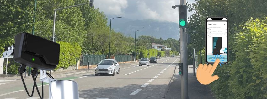
ETAPE 2- AIDE A L’INSTALLATION
- Installer Cap’Mobile :
Android : Cap’Mobile Android
IOS : Cap’Mobile IOS
Windows : Cap’Mobile Microsoft Store
Une fois connecté :
- Dans le menu → Aide à l’installation → Radar Présence
- Indiquer : ligne d’arrêt, hauteur et déport.
- Cap’Mobile fournit ensuite l’angle d’inclinaison recommandé et donne l’information de conformité ou non du site.
Si site non validé → ajuster manuellement les paramètres jusqu’à trouver des conditions d’installation conformes pu nous contacter.
ETAPE 3 – INSTALLATION
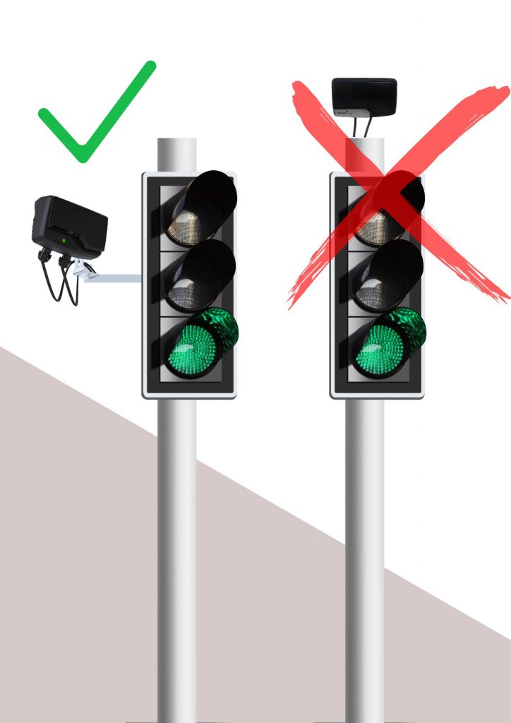
- Fixation latérale obligatoire.
- Régler la hauteur selon Cap’Mobile et fixer l’équerre de déport sur poteau.
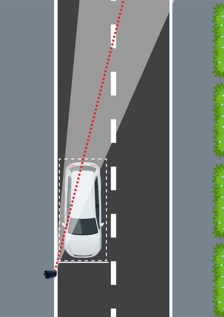
- Monter le radar sur l’équerre et l’orienter selon l’angle préconisé par Cap’Mobile.
- Orientez le radar vers l’arrière du véhicule situé à la ligne d’arrêt.
- Enfin, bloquez l’équerre.
ETAPE 4 – CABLAGE
Respecter le tableau de câblage ci-dessous selon la version :
Si 230 Vac → Protection par disjoncteur type C (2 à 20 A).
Tension de sortie max 30 Vac / 40 Vdc, courant max 50 mA
| TABLEAU DE RACCORDEMENT Presse-étoupe + câble 5m | ||||
| Câble | Fonction | Couleur | Connecteur | |
| 230 V 2 TOR | 2 conducteurs | Neutre | Bleu | Borne 1 |
| Phase | Marron | Borne 3 | ||
| 3 conducteurs | TOR 1 | Vert | Borne 1 | |
| TOR 2 | Blanc | Borne 2 | ||
| Commun | Gris | Borne 3 | ||
| 12/24 V 2 TOR | 5 conducteurs | TOR 1 | Vert | Borne 1 |
| TOR 2 | Blanc | Borne 2 | ||
| Commun | Gris | Borne 3 | ||
| GND | Noir | Borne 4 | ||
| Vcc | Rouge | Borne 5 | ||
Par défaut :
Sortie 1 = contact fermé en hors tension
Sortie 2 = contact ouvert en hors tension
Les deux sorties se ferment en détection
ETAPE 5 – APPAIRAGE
- Ouvrir Cap’Mobile et se connecter
- Sélectionner RFPV dans les produits disponibles
- Appuyer 1 fois sur le bouton d’appairage en face avant du radar
- La LED bleue fixe (10 s) indique la fenêtre d’appairage.
Une fois connecté -> LED bleue clignotante.
ASTUCE : pour éviter d’appuyer sur le bouton en face avant du radar : vous avez 5 minutes après la mise sous tension de celui-ci pour l’appairer.
-> Radars R-Flex à partir de 2026 (n° de série : 26xxxxxx).
Non concernés : les radars antérieurs à ce n° de série.
ETAPE 6 – PARAMETRAGE
Paramètres disponibles : temps d’oubli, portée, réactivité, vitesse min de passage, Led en face avant, état des sorties 1 et 2, fonction présence ou passage, état du contact en détection, temps de maintien. Ils sont configurés par défaut pour couvrir les applications de micro-régulation en encore le feu vert récompense.
STOP-LINE PRESENCE DETECTION RADAR
QUICK START RFPV
STEP 1- SITE STUDY
- A single RFPV radar installed on the pole
- Without road markings: the front of the vehicle must be at the base of the traffic light, and the offset between the traffic light and the roadway must be ≤ 0.5 m.
- With a stop line marked on the road: comply with the traffic light / stop line offset indicated in the table on the right.
| Distance between traffic light and roadside | Distance required between signal light and stop line |
| < à 0,5 m | Between 0 and 6 m |
| 0,5 m-1 m | Between 1 and 6 m |
| 1 m-1,5 m | Between 2 and 6 m |
| 1,5 m-2 m | Between 3 and 6 m |
| > à 2 m | Out of the recommended |
STEP 2 – INSTALLATION GUIDANCE
Download Cap’Mobile :
Android : Cap’Mobile Android
IOS : Cap’Mobile IOS
Windows : Cap’Mobile Microsoft Store
- Once connected, in the menu → Installation Assistance → Presence Radar
- Enter the stop line position, height (3–5 m), and offset.
- Cap’Mobile provides the recommended tilt angle and indicates whether the site is compliant.
If the site is not validated → manually adjust the parameters until compliant installation conditions are achieved.
STEP 3 – INSTALLATION
- Side mounting is mandatory
- Adjust the mounting height according to Cap’Mobile and fix the offset bracket to the traffic light pole.
- Install the radar on the bracket and set the orientation according to the angle recommended by Cap’Mobile.
- Point the radar toward the rear of the vehicle positioned at the stop line.
- Secure the bracket in place.
STEP 4- CABLING
- Connect the cable according to the table below.
If 230 Vac → Protection by Type C circuit breaker (2 to 20 A).
Maximum output voltage: 30 Vac / 40 Vdc, maximum current: 50mA
| CABLING TABLE Gland connector + 5m cable | ||||
| Version | Cable | Function | Colour | Pin |
| 230 V 2 TOR | 2 conductors | Neutral | Blue | Pin 1 |
| Phase | Brown | Pin 3 | ||
| 3 conductors | TOR 1 | Green | Pin 1 | |
| TOR 2 | White | Pin 2 | ||
| Common | Grey | Pin 3 | ||
| 12/24 V 2 TOR | 5 conductors | TOR 1 | Green | Pin 1 |
| TOR 2 | White | Pin 2 | ||
| Common | Grey | Pin 3 | ||
| Ground | Black | Pin 4 | ||
| Vcc | Red | Pin 5 | ||
By default :
Output 1 : Contact closed in power-off state
Output 2 : Contact open in power-off state
STEP 5 – PAIRING RADAR
- Open Cap’Mobile application and log in
- Select the RFPV radar among the the products listed in the apps.
- Press the button on the front of the radar once to pair it with the application.
The blue LED remains fixed for 10s to indicate that pairing is possible.
Once connected -> the blue LED flashes.
NEW : Without pressing the pairing button, you can pair the radar during the 5 minutes following its power-up (radars from 2026 onwards (serial number: 26xxxxxx)).
Not affected -> Radars with earlier serial numbers
STEP 6 – CONFIGURATION
Available parameters: forgetting time, range, responsiveness, minimum passing speed, front LED, status of outputs 1 and 2, presence or passage function, contact status during detection, hold time. These parameters are configured by default to cover micro-regulation and green-light reward applications.