QUICK START
ETAPE 1- MONTAGE
- Distance recommandée entre 2 radars : 50 cm.
- Si 2 radars RFZS : réglage via Cap’Mobile pour changer de canaux et limiter les interférences.
- Le RFZS doit rester sur le canal radio 1 (par défaut) pour si présence d’un radar RFPV.
- Si installation verticale : le radar RFZS doit être installé au-dessus du radar RFPV pied de feu
pour éviter les croisements de faisceaux.
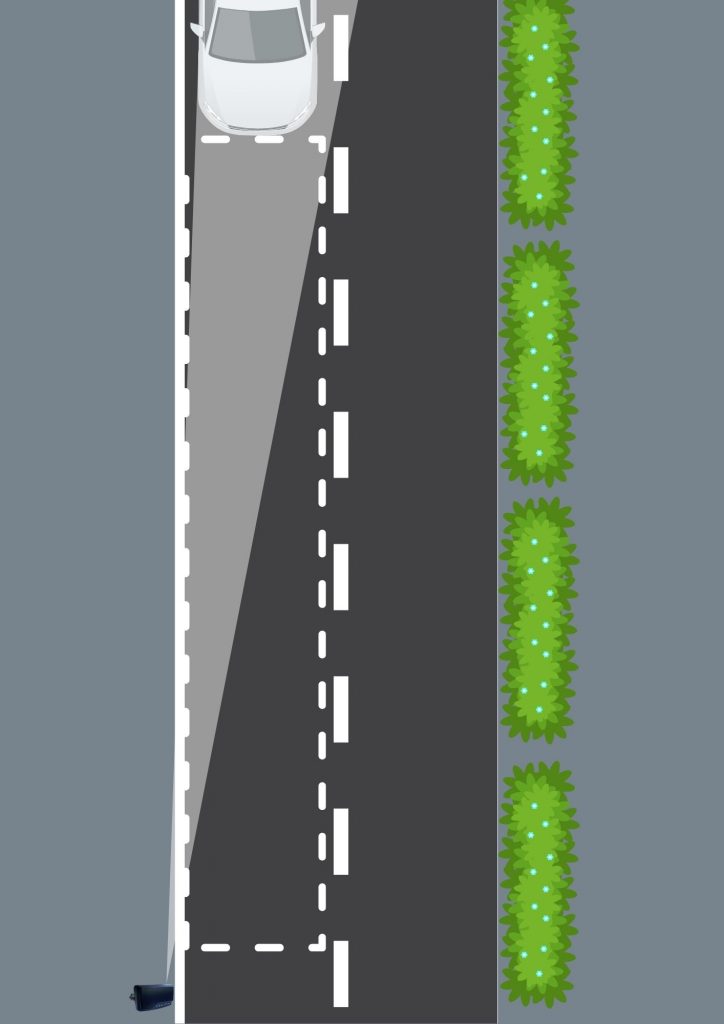
Régler l’angle d’inclinaison en orientant le radar vers l’entrée des véhicules dans la zone de détection, puis bloquer l’équerre de réglage :
ETAPE 2- RACCORDEMENT
- Version presse-étoupe + câble 5m
Respecter le tableau de raccordement ci-dessous selon la version.
(Tension max sur les sortie TOR : 30 Vac / 40 Vdc, et courant max 50 mA)
(Si 230 Vac → Protection par disjoncteur type C (2 à 20 A)). - Version radar avec connecteur étanche
Serrer l’écrou du bornier et du presse-étoupe : 2,5 Nm.
Connecter puis serrer la bague d’étanchéité à la main
A la mise sous tension : clignotement des 3 LED
| TABLEAU DE RACCORDEMENT | ||||
| Câble | Fonction | Couleur | Connecteur | |
| 230 V 2 TOR | 2 conducteurs | Neutre | Bleu | Borne 1 |
| Phase | Marron | Borne 3 | ||
| 3 conducteurs | TOR 1 | Vert | Borne 1 | |
| TOR 2 | Blanc | Borne 2 | ||
| Commun | Gris | Borne 3 | ||
| Câble | Fonction | Couleur | Connecteur | |
| 12/24 V 2 TOR | 5 conducteurs | TOR 1 | Vert | Borne 1 |
| TOR 2 | Blanc | Borne 2 | ||
| Commun | Gris | Borne 3 | ||
| GND | Noir | Borne 4 | ||
| Vcc | Rouge | Borne 5 |
ETAT DES CONTACTS :
– Sortie 1 contact fermé hors tension
– Sortie 2 contact ouvert hors tension
Les 2 sorties se ferment en détection par défaut
ETAPE 3- APPAIRAGE
- Ouvrir Cap’Mobile et se connecter
- « Ajouter radar de zones » et sélectionner RFZS dans les produits
- Appuyer 1 fois sur le bouton d’appairage en face avant du radar
La LED bleue fixe (10 s) indique la fenêtre d’appairage
Une fois connecté → LED bleue clignote
ASTUCE : pour éviter d’appuyer sur le bouton en face avant du radar : vous avez 5 minutes après la mise sous tension de celui-ci pour l’appairer.
-> Radars R-Flex à partir de 2026 (n° de série : 26xxxxxx).
Non concernés : les radars antérieurs à ce n° de série.
Cap’Mobile téléchargeable via :
– Android : Cap’Mobile Android
– IOS : Cap’Mobile IOS
– Windows : Cap’Mobile Microsoft Store
ETAPE 4 – PARAMETRAGE
Paramètres disponibles : distance, vitesse, sens d’approche, priorisation de cible, fonction, type de détection, seuil de vitesse et temps de maintien.
2 zones de détection distinctes peuvent être créées et paramétrées séparément, selon le cas d’usage.
Le véhicule apparait une fois rentré dans la zone.
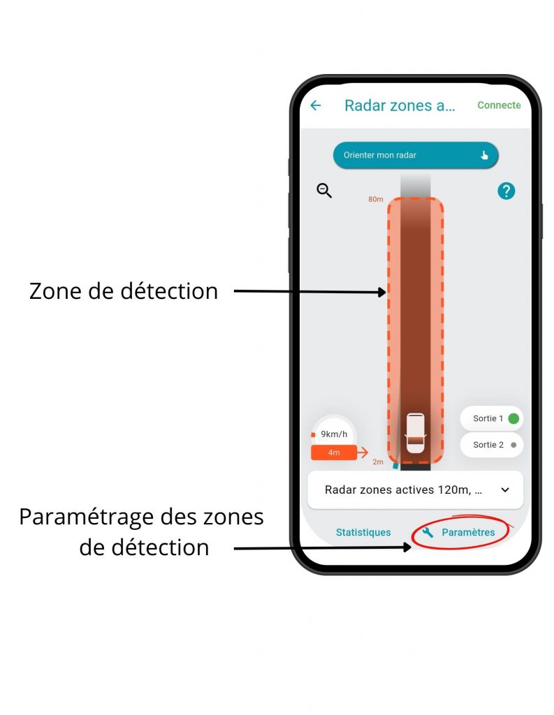
Cliquer sur le bouton « Paramètres » pour paramétrer la zone de détection.
ACTIVE ZONE RADAR – RFZS
QUICK START
STEP 1- MOUNTING
- Recommended distance between two radars: 50 cm.
- If two RFZS radars are installed: configuration via Cap’Mobile is required to change radio channels and reduce interference.
- The RFZS radar must remain on radio channel 1 (by default) when an RFPV radar is present.
- If vertical installation: the RFZS radar must be installed above the RFPV radar to avoid beam overlap
Set the tilt angle by aiming the radar at the vehicle entry area of the detection zone, then tighten and
secure the adjustment bracket.
STEP 2 – CABLING
- With Gland connector + 5 m cable
Follow the wiring table below according to the version
If 230 VAC → Protection using a type C circuit breaker (2 to 20 A).
Maximum output voltage: 30 VAC / 40 VDC, maximum current: 50 mA - Radar with waterproof connectors
Tighten the terminal block nut and the cable gland to 2.5 Nm.
Connect and hand-tighten the sealing ring.
At power-up: LED sequence flashes green → blue → red (×3)
| CABLING TABLE | ||||
| Cable | Function | Colour | Pin | |
| 230 V 2 TOR | 2 conductors | Neutral | Blue | Pin 1 |
| Phase | Brown | Pin 3 | ||
| 3 conductors | TOR 1 | Green | Pin 1 | |
| TOR 2 | White | Pin 2 | ||
| Common | Grey | Pin 3 | ||
| Cable | Function | Colour | Pin | |
| 12/24 V 2 TOR | 5 conductors | TOR 1 | Green | Pin 1 |
| TOR 2 | White | Pin 2 | ||
| Common | Grey | Pin 3 | ||
| Ground | Black | Pin 4 | ||
| Vcc | Red | Pin 5 |
CONTACT STATUS
– Output 1 = closed when unpowered
– Output 2 = open when unpowered
Both outputs close upon detection by default
STEP 3 – RADAR PAIRING
- Open Cap’Mobile and log in
- “Add zone radar” & select RFZS from the products list.
- Press the button on the front panel of the radar once to pair it.
A steady blue LED (10 s) indicates the pairing window.
Once connected to the application → blue LED flashing
NEW : Without pressing the pairing button, you can pair the radar during the 5 minutes following its power-up (radars from 2026 onwards (serial number: 26xxxxxx)).
Not affected -> Radars with earlier serial numbers
Cap’Mobile can be downloaded :
- Android : Cap’Mobile Android
- IOS : Cap’Mobile IOS
- Windows : Cap’Mobile Microsoft Store
STEP 4 – CONFIGURATION
Available parameters: distance, speed, approach direction, target prioritization, function, detection type, speed threshold, and hold time.
Two distinct detection zones can be created and configured independently, depending on the use case.
The vehicle appears when it enters the zone.
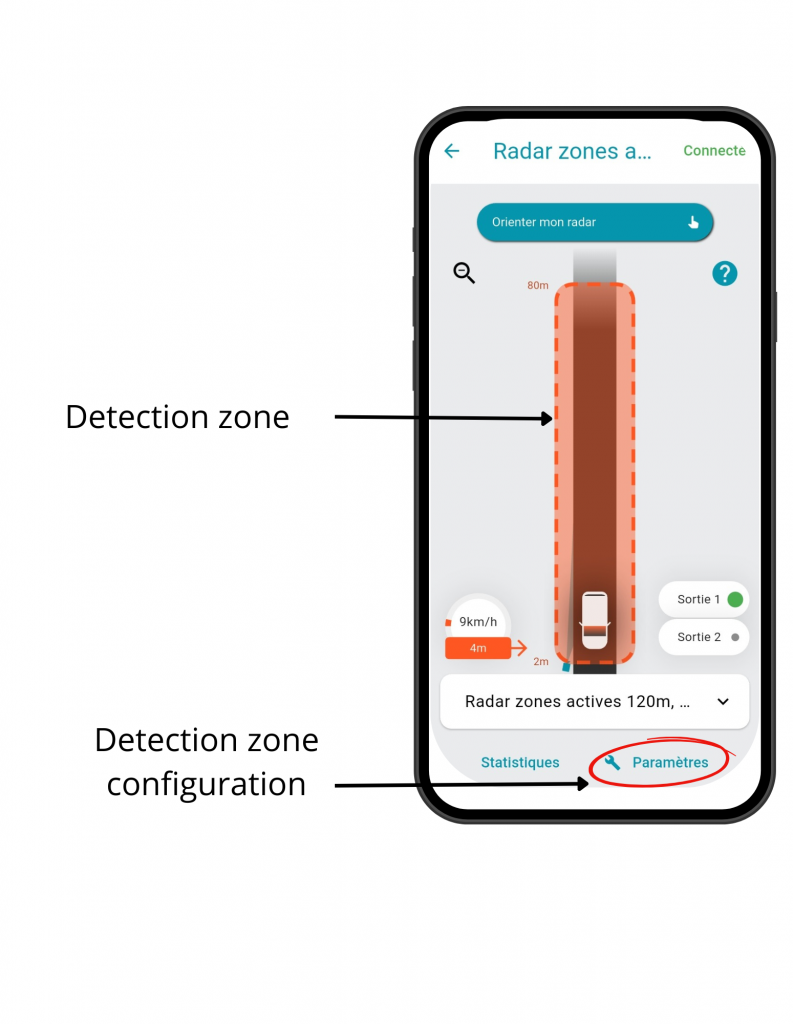
Configure the detection zone by adjusting the distance (start and end points), speed, and detection direction.